1. Simulink Real-Time Set up
1.1. Development PC Program Setup
a. MATLAB 설치(R2016a이상 설치, R2019b 강력 추천!)
- https://kr.mathworks.com/downloads/web_downloads/select_release?mode=gwylf
b. MATLAB, Simulink Real-Time 설치
c. Visual Studio 설치(2017 or 2019, 2017이 지원하는 범위가 더 넓기 때문에 2017추천)
- https://visualstudio.microsoft.com/ko/
- 워크로드 -> C++를 사용한 Desktop 개발 체크
d. MATLAB Support for MinGW-w64 C/C++ Compiler 설치
- https://mathworks.com/matlabcentral/fileexchange/52848-matlab-support-for-mingw-w64-c-c-compiler
e. MATLAB실행 후 mex -setup
f. Microsoft Visual C++ 201X (C) 클릭
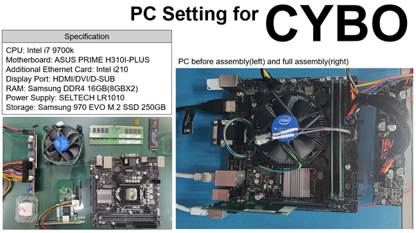
1.2. Target PC Setting
a. Activate PXE Boot option at Bios setting. (Only for Lan Boot)
b. Activate USB Boot option at Bios setting. (Only for USB Boot)
1.3. Development Computer Setting (Only for Lan Boot)
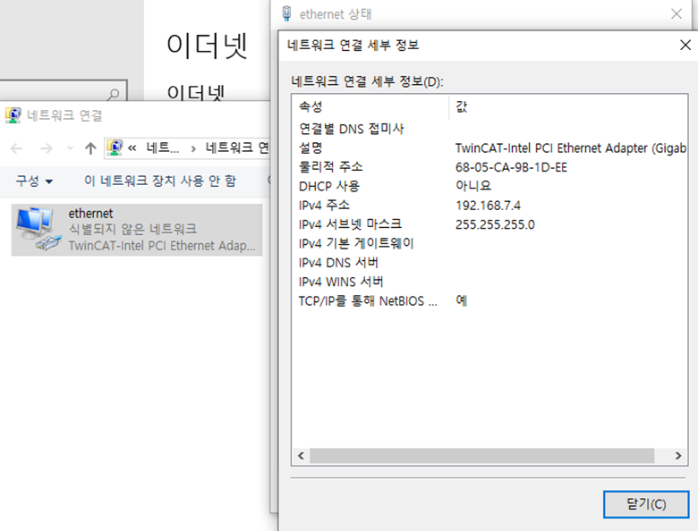
a. Developement Computer의 해당 LAN 포트의 ip주소와 서브넷 마스크를 설정하고 기억하라. (여기선 192.168.7.4 & 255.255.255.0) 게이트웨이는 비워도 된다.
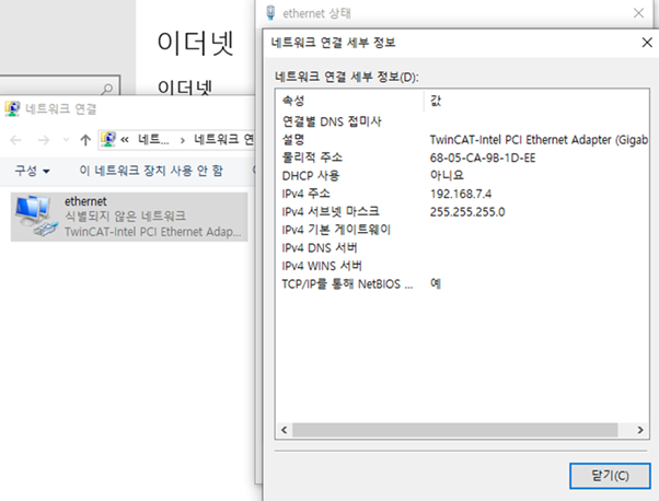
b Development Computer에서 MATLAB을 실행하고 slrtexplr 를 명령창에 입력하면 Simulink Real-Time Rxplorer 창이 나타난다.
c. Add Target을 눌러 Target을 만들고 해당 Target의 Properties에 들어가라.
d. Host-to-Target communication 에서 Target Computer의 ip를 설정해주자. 임의로 설정하되 Developement Computer의 ip 주소와 8 LSB 비트만 달라야한다. (즉, 192.168.7.xxx 의 형식으로 설정) 서브넷 마스크는 Developement Computer와 일치하도록 설정하며, 게이트웨이의 경우Developement Computer의 게이트웨이가 따로 설정되지 않았다면 255.255.255.255로 설정하여라.
e. Target Drive는 auto, Bus type 은 PCI 로 설정하여라.
f. Target Setting 에서는 USB Support, Multicore CPU, Graphics mode 를 체크하여라. (USB Support를 할 경우 안될 때가 있는데 그럴때는 체크해제 하도록, 원인은 모르겠음.) Memory settings 에서는 RAM size auto 로 체크.
g. Boot Configuration 에서는 Boot mode를 Network로 설정.
h. Target Computer를 실행하여라. 성공적으로 실행됐다면 Developement Computer에 어떤 창이 뜰 것이고, 해당 Target을 선택하고 OK를 눌러라. MAC address가 자동으로 입력되고 기다리면 Simulink Real time 이 Target Computer에서 실행된다.
i. Simulink Real-Time Explorer에서 해당 Target을 Connect
j. slrttest를 입력하여 connect가 잘 되었는지 test한다. 다음은 connection이 있을 때 참고할 수 있는 link이다.
- https://mathworks.com/help/xpc/troubleshooting-in-xpc-target.html
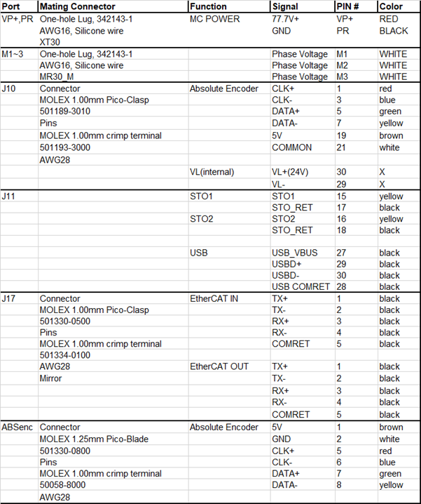
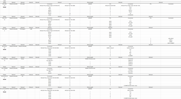
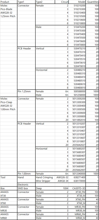
1. Connect Elmo Motor Controller with Simulink Real-Time
1.1. EtherCAT Network Information file (ENI file) Generation
- Set up Visual Studio (Visual studio 2017 is rcommended)
https://visualstudio.microsoft.com/
- Set up Twincat3
https://www.beckhoff.com/twincat3/
download -> software -> twincat 3 -> TExxxx | Engineering
TwinCAT 3.1 – eXtended Automation Engineering (XAE) -> download & set up
- Elmo Slave Information (ESI) Download
Support -> Resources Center -> Gold Drive Links -> Version ---.zip download
ECAT********.xml is ESI file of Elmo Gold drive
Put ESI file at C:\TwinCAT\3.1\Config\Io\EtherCAT
- Run TwinCAT 3
C:\ProgramData\Microsoft\Windows\Startmenu\Programs\Beckhoff\TwinCAT3
Run TwinCAT XAE (TcXaeShell)
- Make ENI file with TwinCAT 3
New TwinCAT project
(Next to Debug) TwinCAT -> show realtime ehternet compatible devices
Click LAN port -> install
(menu bar) TWINCAT -> Scan or (See the picture below) Solution Elplorer -> TwinCAT Project -> I/O -> Devices -> Scan
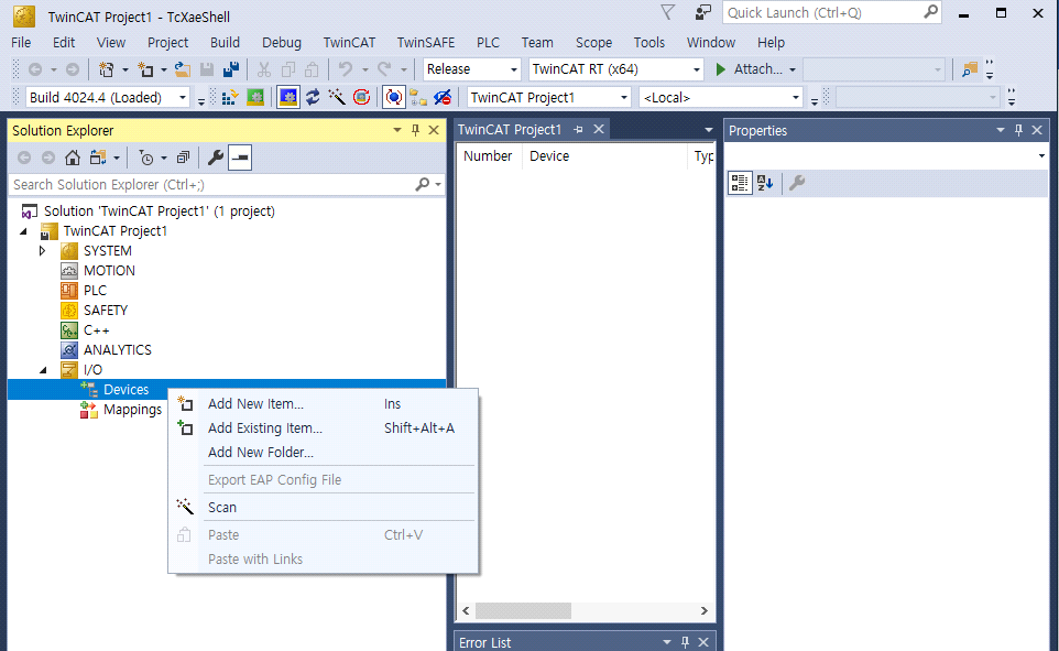
- If there is ‘All devices may not automatically be found’ message -> click OK
- New I/O devices have been found -> Check check-box and click OK
- If there is ‘Scan for boxes’ message -> Click Yes -> EtherCAT devices appears at Solution Explorer
- If there is ‘Free run mode’ message -> Click NO
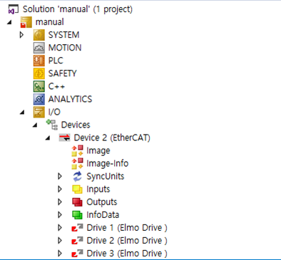
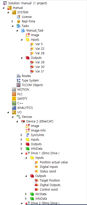
- Solution Explorer reflects EtherCAT Network connection (following picture)
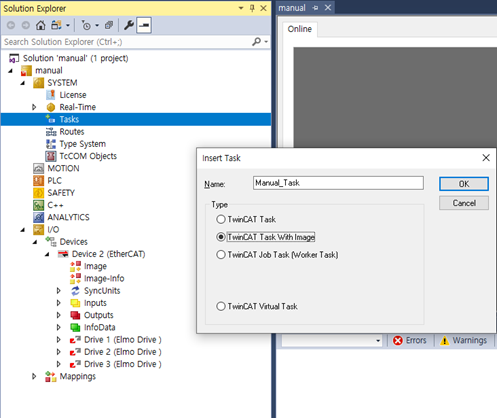
- Solution Explorer -> SYSTEM -> right click Tasks -> Add New Item…
- Insert Task -> Select TwinCAT Task With Image -> set name of task -> OK
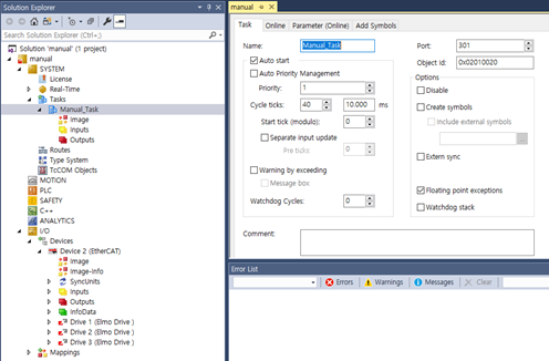
- Double click generated task(following picture Manual_Task)
- Match the Cycle Ticks on the Task tab to sampling time of Simulink Real-time(SYSTEM -> REALTIME tap -> system clock) See the Simulink Block example for setting the Sampling Time.
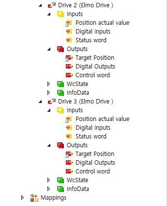
- Solution Explorer -> Devices -> Device(EtherCAT) -> Drive 1 or Drive 2 or Drive 3 -> Check the Inputs or Outputs(following picture). This information is the Process Data Object (PDO). PDO means the information exchanged between EtherCAT slave and EtherCAT master. To change the PDO, see the PDO setting.
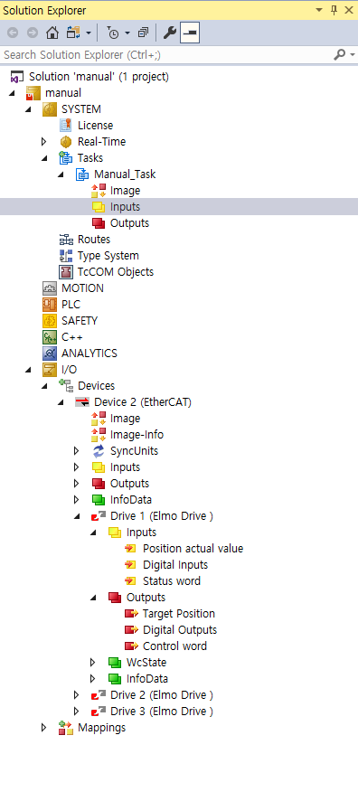
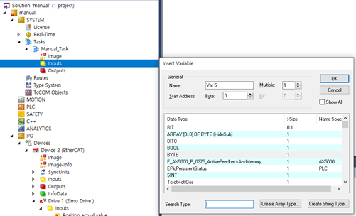
- Solution Explorer > Tasks > Task > Inputs 를 오른쪽 클릭하고 Add New Item... 을 클릭하면 Insert Variable 창이 뜨는 것을 볼 수 있다. Data Type을 설정해주어야 한다. 일단 Insert Variable 창은 다시 꺼라.
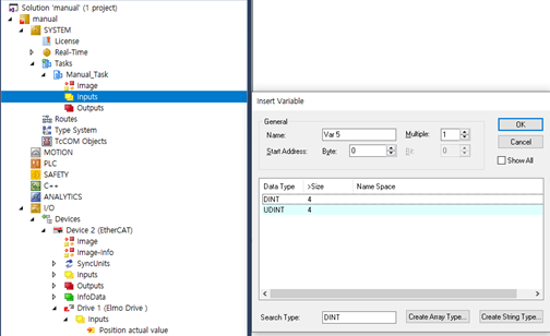
- Solution Explorer > Devices > Device (EhterCAT) > Drive 1 or Drive 2 or Drive 3 > Inputs 의 하위 요소 중 하나(여기선 Position actual value)를 한 번 클릭해라. 다음과 같이 오른쪽에 설정창이 뜨고, 그 중 Type 에 입력된 값을 기억해라(여기선 DINT).
- 이 값을 Solution Explorer > Tasks > Task > Inputs 를 오른쪽 클릭하고 Add New Item... 을 클릭했을 때 뜨는 Insert Variable 창에서 Search Type 에 쓰고 해당하는 Data Type 을 선택하고 OK 를 눌러라. (Multiple을 활용하면 여러개 만들 수 있다.)
- 이전에 확인했던 Solution Explorer > Devices > Device (EhterCAT) > Drive 1 or Drive 2 or Drive 3 > Inputs 의 하위 요소 중 하나(여기선 Position actual value) 를 다시 한 번 클릭하고, 오른쪽에 나타나는 설정 창에서 Linked to... 를 클릭해라
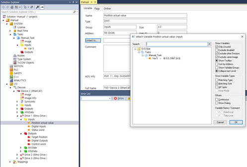
- 만들었던 Input에 해당하는 값(여기선 SYSTEM > Tasks > Manual_Task > Var 5)을 클릭하고 OK 를 누른다.
- 모든 Drive에 속해있는 Inputs 와 Outputs 에 속한 요쇼 중 최소한 하나씩은 이짓을 하여서 다음과 같이 Task를 만들어야 한다.
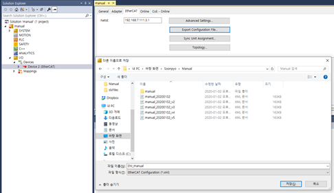
- Solution Explorer > I/O > Devices > Device (EtherCAT) 을 클릭하고 나타나는 창의 EtherCAT 탭에서 Export Configuration File 을 클릭하여, .xml 파일 저장. (요놈이 ENI 파일이다.)
'Cybo Development > Planner' 카테고리의 다른 글
| 20200104 Simulink Real-Time Connection 1 (0) | 2020.01.06 |
|---|---|
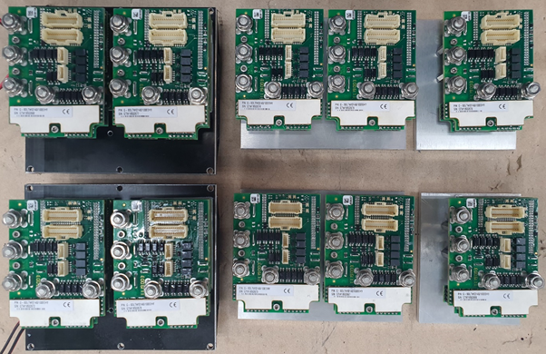
| 20200103 Elmo Gold Solo Double Twitter Installation 2 (0) | 2020.01.05 |
| 20200101 Elmo Gold Solo Double Twitter Installation 1 (0) | 2020.01.02 |
| Plan20181231 & Elmo Gold Solo Double Twitter (0) | 2019.12.31 |